I have half a dozen recording devices to connect. Unfortunately my Mission Cyrus amplifier only has provision for one tape recorder. To solve this problem I built This.
I currently use an excellent Sony SB-300. Unfortunately It’s three machine capability won’t cut it for me anymore because I need to connect up the following:
- Sony TC-377 Open reel
- Grundig TK-14 Mono Open Reel
- Sony TC-204 Cassette deck
- Yamaha KX480 Cassette deck
- Sony MDS-JE480 MiniDisc recorder
- Laptop ADC/DAC for recording
- Wien 8TD3 8 Track cartridge player.
Various switch boxes have been produced commercially for connecting several tape recorders into an amplifier which has provision for only one. Most also allow for copying between machines. Unfortunately all but the most expensive are limited to 3 recorders.
I can condense my main requirements down to the following:
- Play back any recorder through the amplifier.
- Record the amplifier output onto any or all recorders.
- Record any recorders output to any or all of the other recorders.
- Select output to amplifier for listening.
- Select output for external monitoring output for headphone amplifier and VU meters.
- At least 7 channels. But if I can make it expandable that would be good?
- And Finally, be Easy to use.
Good luck with that lot.
The HiFi Engine website has a comprehensive library of user and service manuals as well as a lively forum community. This was a goldmine of information. I was able to study the circuits of various commercial units including the Sony SB-300 and SB-500. It quickly became apparent why most units only go up to 3 channels. Rotary switches have a limited number of contacts. Once you get past a dozen you are into a world of expensive customised multiple wafer switches or complex interlocked push buttons. This quickly led to the conclusion that if rotary switches are to be used 3 is the limit
One switch box which bucked the trend is the Realistic 42-2105 “Tape Control Center” . This uses a different approach. Instead of complex routing with multi-way rotary or push buttons it uses simple 3 way switches. Lots of them.
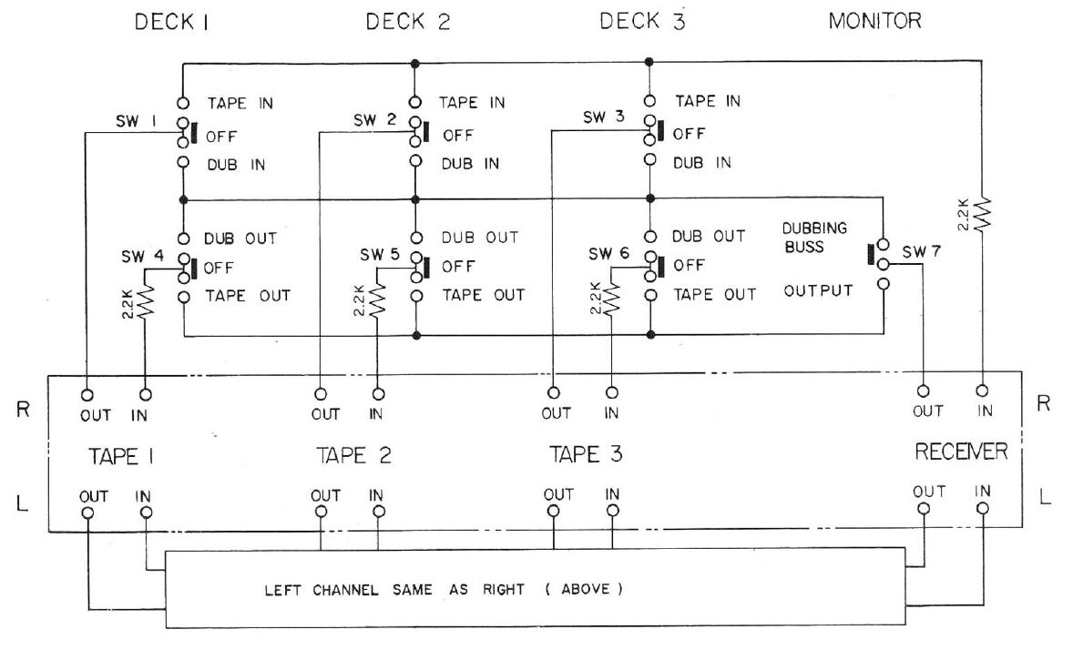
The simple idea which makes this work is a set of common connections (called a “bus” in electronics speak). An “input bus” makes the output from the amplifier available to be switched to the input of any or all of the recorders. An “output bus” can be fed from any or all of the recorders outputs. These two buses give the means to record to or play back from any of your recorders.
This is great if the source is your Amplifier and you are only playing back to the amplifier. In order to record from one recorder to another a “dubbing bus” is required. Recorder outputs and inputs can be connected to this, so you have a route to pass audio between recorders.
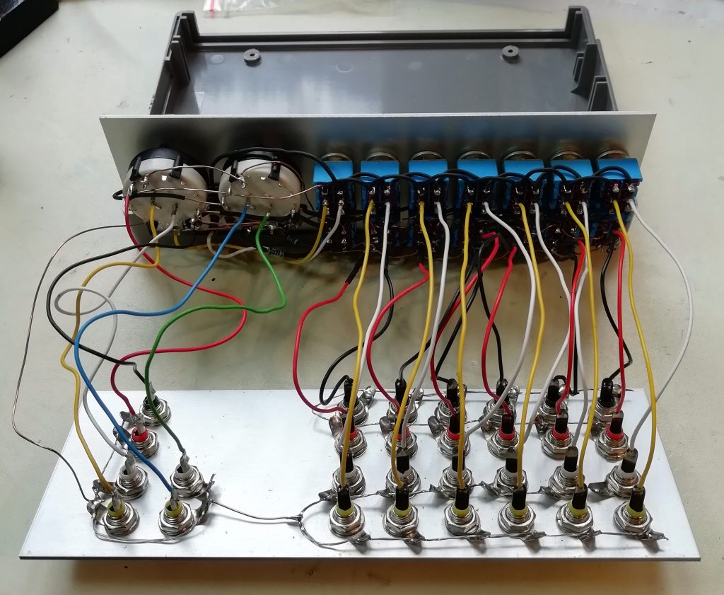
It was this circuit idea which I extended to build my seven channel switcher. The buses are hard wired simply by soldering wires between the switches. It took ages. Each recorder has a pair of toggle switches. The top one selects what is connected to the recorders inputs, the bottom one selects what the outputs connect to. This unit has 7 pairs of switches. If, in the future, I want to expand it for even more recorders I just need to extend the 3 pairs of bus wires out to another box, via a suitable connector.
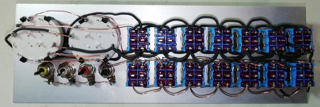
With the back panel added the wiring is even more complex. 2k2 ohm resistors are added to all inputs to prevent potentially damaging overload. Six sets of tape recorder sockets are on the back panel, with the 7th on the front to facilitate temporary ad-hoc connections.
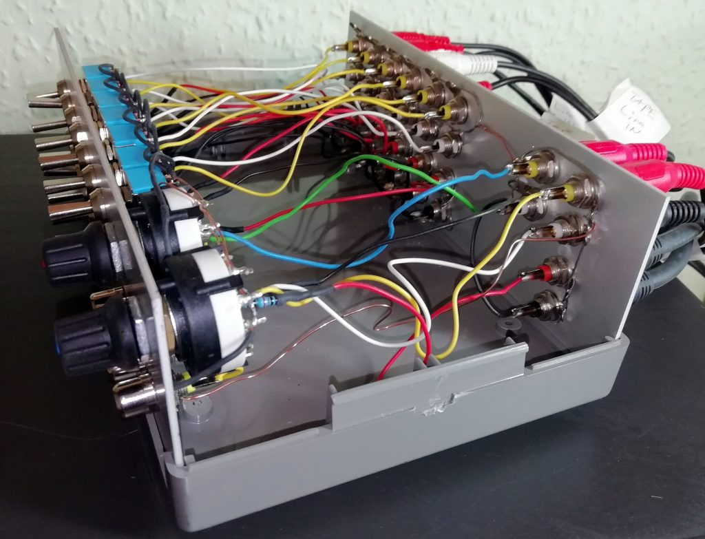
The monitoring section is slightly different to the Realistic. I have used a rotary switch so that I can select any of the three buses. Two rotary selectors are provided, feeding separate outputs. This is because I need another output to feed a separate headphone amplifier and VU meters. This needs to be independent of the monitor output fed back to the amplifier.
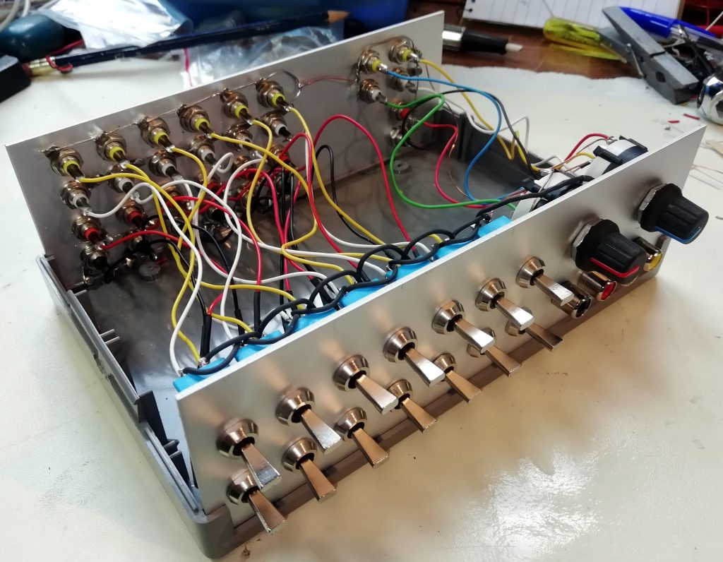
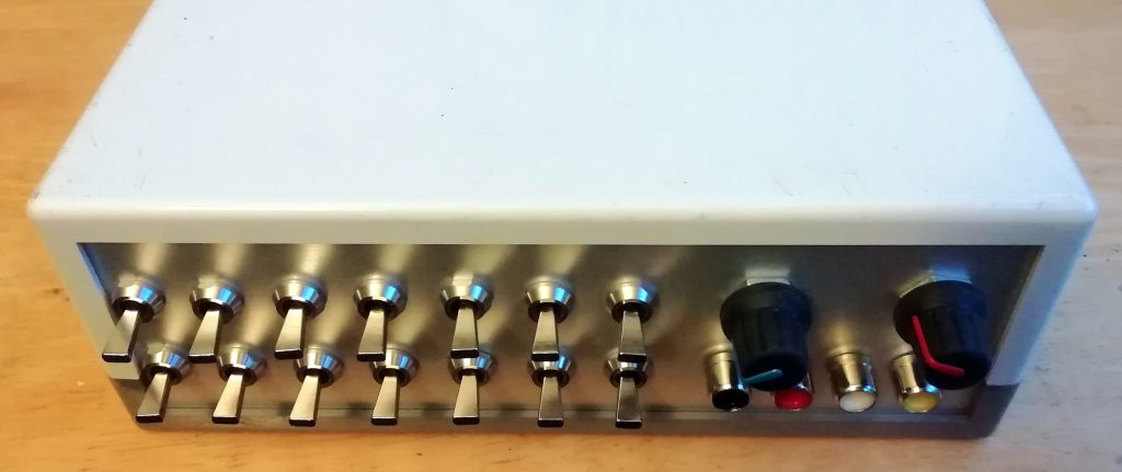
Aesthetics are important for a unit which will live in the house as part of the Hi-Fi. I chose paddle type switches, rather than the common 3 way miniature toggle. I also added nice ornamental nuts. This added considerably to the cost, given that there are 14 switches. For the sockets I used multiple colours. Black and red for left and right inputs. White and yellow for outputs. I’m not really happy with the knobs yet, but i do have several other options to try.
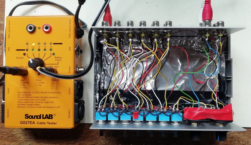
Before finally clipping the box together I added internal shielding constructed from pie trays and fitted in place with a hot glue gun. No attempt was made to run wires neatly. This was deliberate. Parallel wires are likely to electrically interfere with each other. Shielded internal wiring wasn’t going to happen either, unless it proved necessary. I only have so much patience.
That’s an awful lot of combinations of switches and connectors to get right. To test it I use my audio cable continuity tester. This let me connect up 4 connectors simultaneously and than try all the relevant switch combinations. It still took me an hour to work through it all systematically checking for open or short circuits.
This was a long time in the making. Loads of hand wiring and quite a lot of precision drilling and cutting out. The cost was also significant, especially the switches and hardware. All on all I spent over £60. It does however do the job very well.
I have described how to use the switch box in another article.