This is my recorder selection switch box.
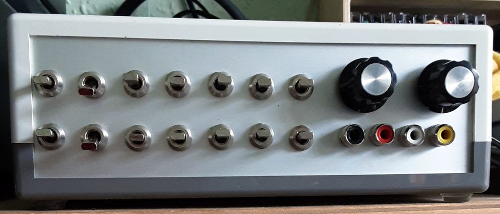
That’s a lot of controls. Here I describe how to use it.
In an earlier article I described the design and construction of a selector switch for many tape recorders.
That article was quite long enough, so I held off describing how to use it for a separate article.
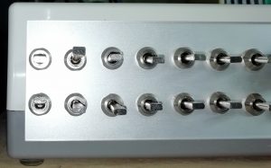
A bank of 14 switches control connection to the 7 recorders which can be connected to the switch box and a couple of knobs control what gets sent out to the amplifier or other monitor.
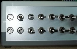
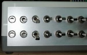
Recorder Input switches
The top row of switches determines the input connection to the recorders
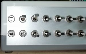
- When UP the recorder(s) is connected to the dubbing bus
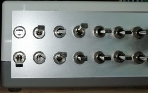
- In the center position the recorder(s) is not connected (off)
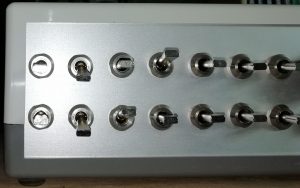
- In the DOWN position the recorder is connected to the Amplifier.
Recorder Output switches
The lower row of switches determines determines the output connection of the recorders
- When UP the recorder(s) is connected to the dubbing bus
- In the center position the recorder(s) is not connected (off)
- In the DOWN position the recorder is connected to the Output section.
Monitor Selector knobs
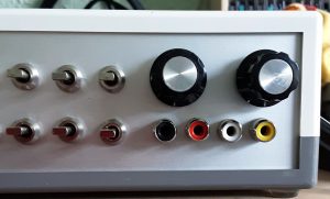
The knobs have three positions and determine the signal being passed to the two monitor outputs.
- Position 1 connects to the output from the recorder(s)
- Position 2 connects to the input from the amplifier
- Position 3 connects to the dubbing bus
Two knobs are provided to feed the two separate monitoring outputs.
The right hand output is used to connect to the Amplifier tape monitor input. This control is normally left in position 1 so that you can listen to the recorder which you have selected with the lower bank of switches.
The left output is connected to a headphone amplifier and a meter bridge. This control is normally left in position 2 so that you can listen to the amplifier on headphones or watch the meters dancing.
Using the Selector Switch
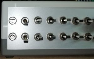
Recording from the Amplifier
Flip down the appropriate upper switches. If you want to monitor the recording, also flip down the lower switch.
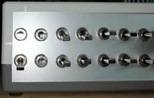
Dubbing recordings
Flip up the appropriate upper switches to set the machines which are to record. Flip up the appropriate lower switches to select the machine which is to play.
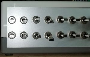
Simultaneous functions
Some complex scenario’s are possible by using the dubbing bus and both the input and output bus.
That’s all there is to it.