My 8 track player has developed a problem.
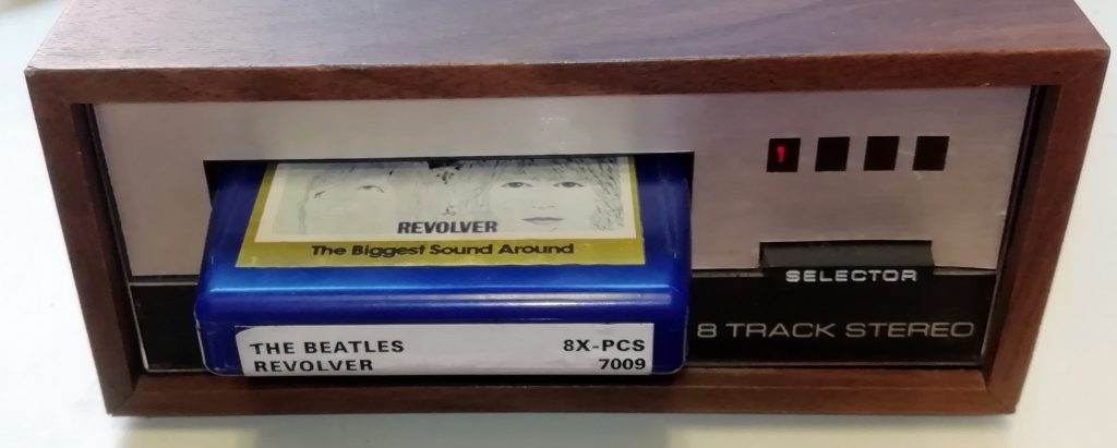
It doesn’t always switch tracks properly at the end or when you press the selector button. So, what has that got to do with a flushing toilet?
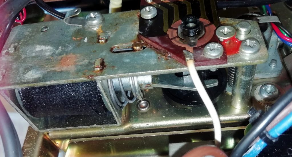
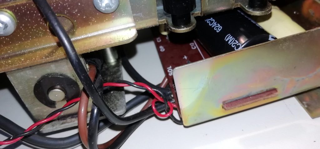
This the mechanism that moves the tape head to align it with the desired tracks. On the right is a black plastic rotating cam. This is pushed round by 1/4 turn at a time by the metal fork in the middle. The fork is moved by a big solenoid on the left. The solenoid is an electromagnet. When current is passed through the coil of wire a magnetic field s produced which pulls the iron core into the coil. This pulls the fork back and compresses the spring. When the current is switched off the spring pushes the fork back against the cam. The problem here is that this mechanism isn’t running smoothly. The solenoid doesn’t always pull the fork back far enough.
As is usually the case with old audio gear, part of the problem is muck and dried out lubricant. I sorted that and it did improve matters. I also thoroughly cleaned the tape contacts and the selector switch. However the solenoid still wasn’t getting quite enough clout.
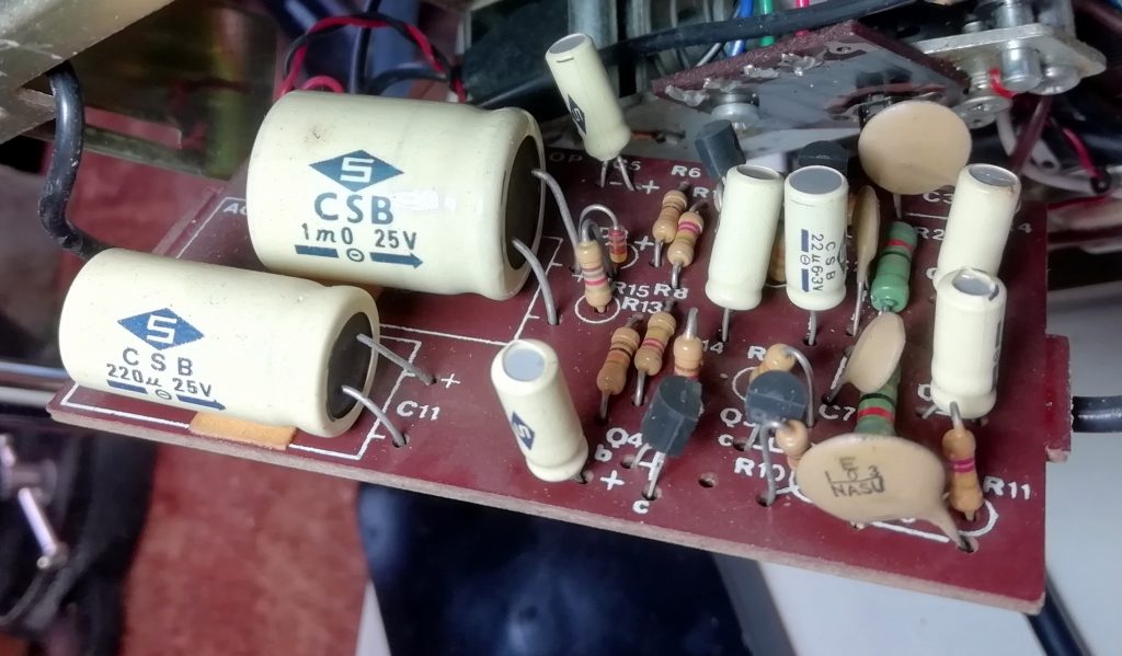
I’m now suspecting a problem with the electronics. On this machine the electronics, what there is of them, are all on one small circuit board which easily clips out. Most of what you see on the right is a pair of simple audio amplifiers to boost the low level left and right audio signals from the tape head to a level which is suitable to drive your HiFi Amplifier. We are concerned with the circuit around the larger of the two capacitors on the left.
As soon as I started to look at this circuit I realised what was going on. Solenoids require a lot of current to create a large enough magnetic field to do the job. Indeed so much current that, if it were allowed to keep flowing it would burn out the coil.
The way it works is to store charge in a capacitor. When required the capacitor is connected across the coil and it discharges through the coil. This gives a massive current but only for a short time. Ideal. The current feed to the capacitor is limited, so it takes a second or two to charge up. This also limits the current that can continue to flow into the coil if the selector switch is held down, or the tape happens to jam with the foil bridging the contacts!
Our problem here is the big yellow capacitor in the middle of the picture. Rated at 1000 uF 25 V, I’m not convinced it’s still up to that. I don’t have the means to test capacitors, but having a rummage in my spares box I found a 4700 uF 35 V capacitor. It fits physically, has a bout 5 x the required capacity and a plenty high enough voltage rating.
Here you see it, the black one, with the circuit back in the player and the solenoid on the left. I works great now.
Not for the first time (see motor refurbishment) I recognised technology familiar to railway modelling. Model railways use sturdy solenoids to operate points (turnouts). The same problem exists and many a “turnout motor” has fried due to this problem. To understand the benefits and operation of the capacitor discharge circuit for operating solenoids I once read a magnificent layman’s description in a Model Railway magazine.
The article likened the circuit to a flushing toilet. The bowl is the solenoid and the cistern the capacitor. The cistern slowly fills with water. When you are ready you pull the chain. A deluge of water is deposited into the bowl, hopefully doing what is required. However the deluge stops, so you don’t get a rather unpleasant overflow situation.