My original plan to wind my own pickups was thwarted because I was unable to source the necessary magnets. Taking the easy, but expensive route I purchased a pair of the “must have” pickups of the time. Di-Marzio “Dual sound”. This is basically the four conductor version of the then popular “Super Distortion” hum-bucker pickup. The extra wires allow you to configure the two coils of the hum-bucker in various ways, depending on your ingenuity and the switches available. I wired each to a miniature toggle switch, as described by Di-Marzio, so that the coils can be set to parallel or series wired. The signals from switch are then combined with a standard Gibson style 3 way toggle so that you could have either or both pickups in circuit.
This much remained constant, but the rest of the circuit changed through 3 versions as my knowledge and taste developed.
Version 1.
In order to get “out of phase” sounds with both pickups on, the bridge pick-up has an additional miniature toggle to reverse its phase relative to the neck pickup.
The original magazine article had described a circuit for active electronics to provide volume base and treble control. Bear in mind that this was the late 1970’s and “actives” were the latest thing to have. What should have been a cool feature was actually a pain. It was far too noisy and it distorted in a horrible way if you played too hard. It also ate batteries like a drumming bunny.
With the benefit of hindsight, oh and a 1st class degree in electronics, I now realise that the circuit was quite crude and had been lifted directly from the data sheet of the ua741 Integrated circuit at it’s heart. The 741 is an amazing and versatile IC when correctly applied. Here it was too noisy and the circuit design did not allow for the high signals which come out of the Di-Marzio pickups. With the intended low power pickups it would probably have been fine. At the time I did not understand any of this and couldn’t fix it. hence ..
Version 2.
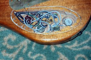
I removed the active electronics, but retained the pickup series / parallel and phase switching. Each pickup has a 470K log pot for volume. The two volume pots feed the output jack via a 3 way Gibson style pickup selector switch. The Third pot is not used.
This is the state in which the guitar spent about a dozen years.
Version 3.
I decided that I didn’t use the phase switch, ever. I also wanted to experiment with single coil type sounds. The Di-Marzio “dual sound” series/parallel switching is good and I wanted to retain this. The challenge then was to retain the series/parallel switching for each pickup, but use the now redundant phase switch as a coil tap switch.
A hum-bucker pickup usually has both coils connected in series to maximise the output voltage. Tapping this is easy. You just arrange a switch to short out one coil. the problem I have is that with “dual sound” wiring the hum-bucker coils can be in parallel. Now if you short out a coil you actually short out both and kill the output altogether. To tap a “Dual Sound” which is set to parallel you actually need to disconnect one coil rather than shorting it out. I eventually came up with the circuit shown. Each pickup has it’s own mode switch (previously the dual-sound switch) and a second switch, the tap switch, selects single coil or hum-bucker. In practice only one tap switch is fitted, with each hum-bucker using half of it. With the tap switch in the hum-bucker position the mode switches act as series/parallel switches to give the “Dual sound”.
The interesting behaviour happens when the tap switch is in the single coil position. The hum-bucker is tapped to only use one coil.
Careful study of the circuit shows that if the mode switch is in the series position, then coil C2 is shorted out, leaving just C1 in Circuit. If the mode switch is in the parallel position, then the C1 coil is disconnected, leaving just C2 in circuit. Repeat the circuit for the neck pickup and we are in business, but we can do better than that.
Consider how a hum-bucker works. A hum-bucker reduces noise by having two coils which are wound in opposite directions. Any electrical interference picked up by one coil is also picked up by the other, but the opposite way round. When you add the signals together (by connecting in series or parallel) the interference is cancelled. You would expect this setup to cancel the signal due to the guitar string as well, but the string signal depends on the magnets in the pickup. By arranging the magnets with opposite polarity in the two coils you end up with string signals which add together, and interference signals which cancel. This is why hum-buckers give a high output with low noise. In practice, as long as you have a C1 and a C2 in circuit together you get hum cancelling.
With the tap switch set to hum-bucker you always have noise cancelling configurations. Setting the switch to “single” can also give noise cancelling if both pickups are on and one is tapped to give a C1 and the other to give a C2. Both volume controls also need to be at the same level. If we make the circuit for the neck pickup a mirror image of the bridge pickup then, if both mode switches are in the same position, one pickup will tap C1 while the other taps C2. This gives more intuitive switching in practice.
The switching table illustrates this.
| Switches | Bridge Pickup | Neck Pickup | Noise Cancelling | ||||
|---|---|---|---|---|---|---|---|
| Common Tap | Bridge Mode | Neck Mode | Coil C1 | Coil C2 | Coil C1 | Coil C2 | |
| Hum-bucker | Series | Series | In Series | In Series | Always | ||
| Hum-bucker | Parallel | Parallel | In Parallel | In Parallel | Always | ||
| Single | Series | Series | On | Off | Off | On | Sometimes |
| Single | Parallel | Parallel | Off | On | On | Off | |
| Hum-bucker | Series | Parallel | In Series | In Parallel | Always | ||
| Hum-bucker | Parallel | Series | In Parallel | In Series | Always | ||
| Single | Series | Parallel | On | Off | On | Off | Never |
| Single | Parallel | Series | Off | On | Off | On | |
Version 4 2025 rework
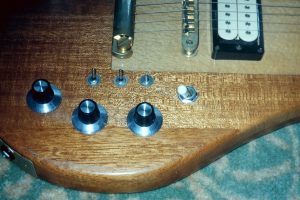
In 2025 I did some work on the guitar. As part of this the electrics were changed to accommodate new knobs. The new pots fitted were 250K, rather than the 500K previously fitted and the volume pots are wired for independent operation. The changes were because the wiring kit I ordered came with that configuration, despite the listing saying otherwise. It works well.